


Assembly of the System Copal 4 frameless system – step by step
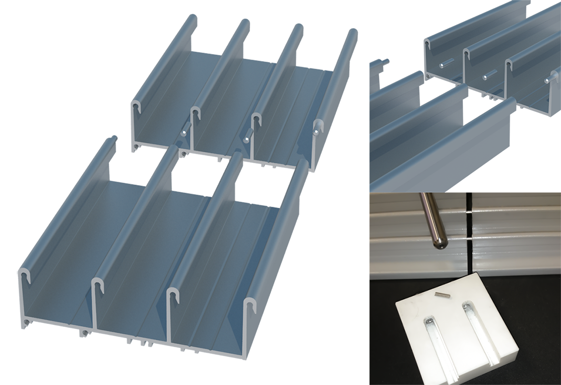
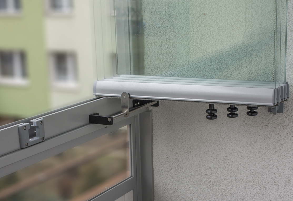
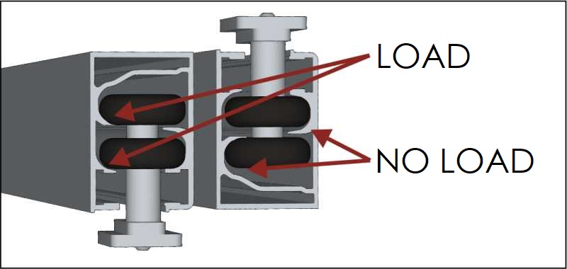
1. Loading the enclosure by shifting elements is transferred by the top guide bar.
2. Mount the top guide bar to the ceiling, using the prefabricated holes and pins or screws.
3. Position the bottom guide bar on a balustrade or a ledge and mount the first lock profile.
4. Screw the bottom guide bar to the ground and then mount the second lock profile.
Guide bars may be connected to each other with straight or angled connectors. The connector is to be screwed to the guide bars with screws.
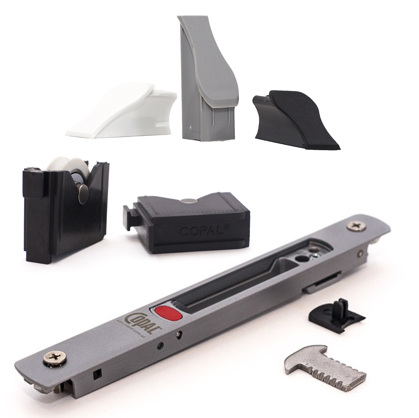
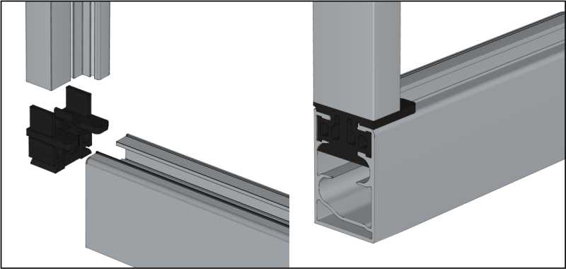
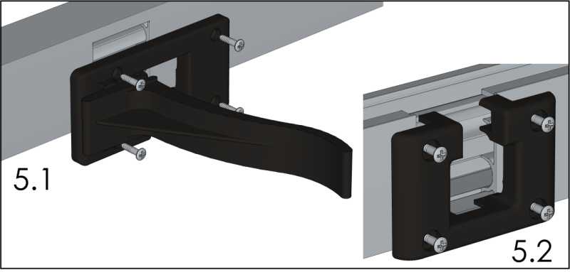
5. In order to mount the first top–hung panel, remove the plugs from the guide bar – top (fig. 5.1) and bottom (fig. 5.2).
6. Put the bottom and the top lock aside to the opposite side of the outlet (fig. 6.1).

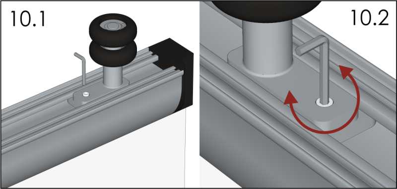
7. Mount the top–hung panel and adjust it with an Allen wrench in a way that allows the panel to open smoothly (fig. 10.1 and 10.2). Put the locks back (fig. 7.1) and block them with a screw in a marked hole (fig. 7.2).

8. Fit the top–hung and slide panels, starting from the first one. The process of fitting the panels is illustrated in the picture below (fig. 8.1).

Once they are fitted in, leave the panels open (fig. 8.2).

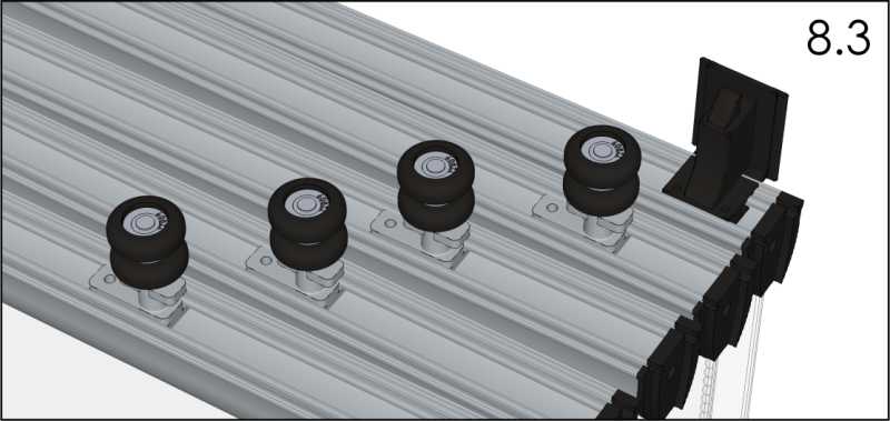
Roller layout, as shown in figure 8.3, means that the order of the panels is correct.
9. Mount the guide bar plugs – the top and the bottom one (fig. 5.1 and 5.2).
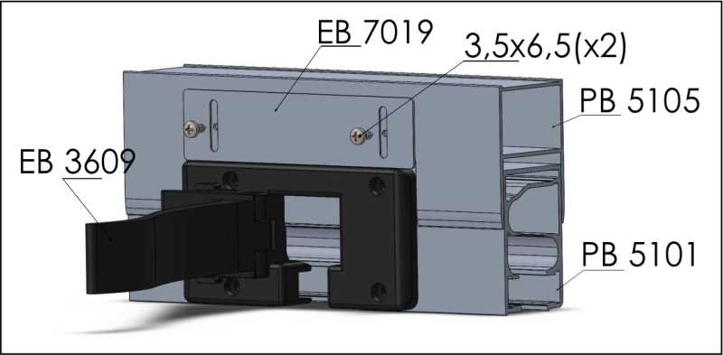
NOTE: In the case of assembling the enclosure with a telescopic guide, the cover (EB 7019) is screwed only after the guide is mounted and adjusted. Drill the hole for the 3.5 x 6.5 screw with a 2.8 mm drill bit.
10. Adjust panels, from the first to the last one, with Allen screws located within the rollers (fig. 10.1 and 10.2).
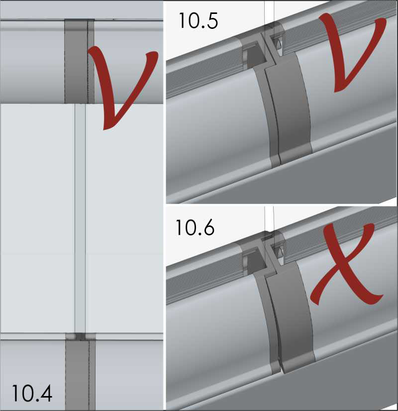
Note: Rollers have to be adjusted in such a way that they touch the panel guide bar while opening/closing the enclosure (fig. 10.3)

The distance between glass edges should be 4 mm along the entire sheet of glass (fig. 10.4). Plug edges have to be facing one another (fig. 10.5 and 10.6).
Note: depending on the lock, choose the appropriate assembly procedure.
E4050 aluminum lock
11. Start the assembly of a lock by drilling the holes in the bottom guide bar (fig. 11.1).

Φ 3.5 hole drilled in the guide bar for the 4.2 x 13 screw.
The spacing of holders’ mounting may change, depending on the guide rod length.
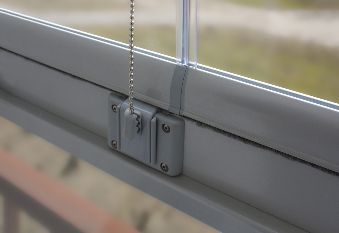
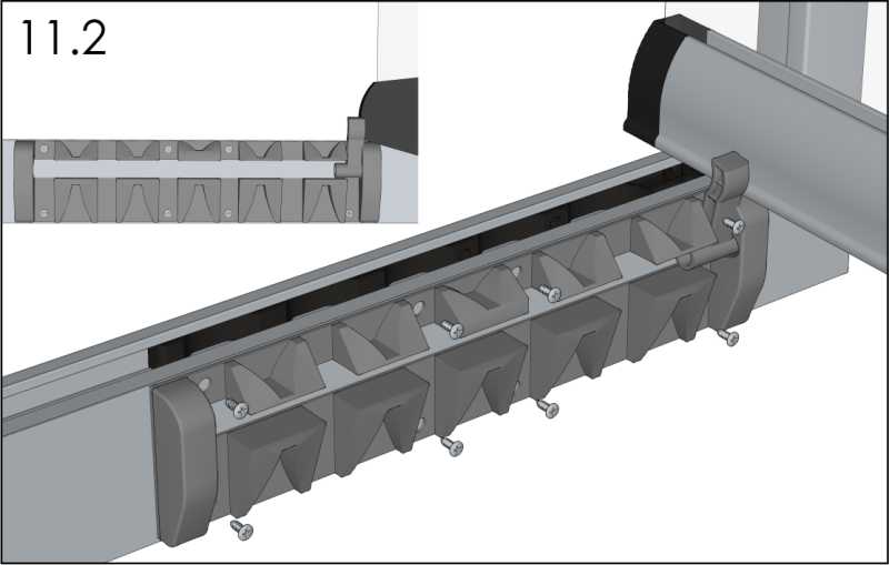
EB4110 plastic lock
11. Start the assembly of a lock with opening the first panel. There should be no space between the fully open first panel and the pin (fig. 11.2). The lock should face the upper edge of the guide bar perfectly.
12. Seal the structure with silicone and, optionally, mount the transparent PVC gaskets between glass panels.